eTRIx: Roboteering
Restored and Annotated — 2026 Edition
A note about this edition
The original manual is preserved substantially as it was written in the late 2000s — voice, jokes, strange capitalization, iPods, movie references and all.
The annotations are new.
They come in four flavors:
2026 CORRECTION — something in the original is factually wrong.
2026 CAVEAT — the intuition is useful, but the literal explanation goes too far.
2026 UPDATE — the technology, history or context has changed.
2026 ASIDE — present-day Omar cannot resist interrupting younger Omar.Think of them not as errata, but as a conversation across nearly twenty years.
Image source note
Diagrams and reference images in this edition were extracted from the original
e-trix-manual.pdfand restored only enough for readable web presentation. Captions describe their role in the original manual; the surrounding 2026 notes remain editorial annotations.
Preface to the 2026 Edition
This manual was written a very long time ago.
Well, technically not that long ago.
But long enough ago that the iPod was still an object capable of making a human “feel complete,” people regularly bought electronic components from shops instead of clicking a button on a website, and the 555 timer still seemed immortal.
Actually, the 555 timer is immortal.
So perhaps some things survive.
I wrote the first version of this manual while teaching robotics to engineering students in India in the late 2000s. I was in my twenties, travelling constantly, teaching hundreds of students at a time, building robots out of whatever we could get our hands on, and trying very hard to convince engineering students that engineering was not, in fact, the art of solving examination problems.
That part I still believe.
The central idea of this manual was simple:
Do not begin with the name of the tool. Begin with the problem that makes you wish the tool existed.
If you want to cut a circle from wood, struggle with the screwdriver first.
Then I show you the saw.
If your robot is confused by ambient infrared, experience the confusion first.
Then we talk about modulation.
If you need to remember a state, discover that your circuit has forgotten what happened.
Then I show you the flip-flop.
If you need to compare two voltages, first become annoyed that your circuit cannot make a decision.
Then we talk about the op-amp.
The point was never to replace a proper electronics textbook.
In fact, the original manual says explicitly that you should eventually go back to those large, frightening books on your shelf and read them again — only this time knowing why the ideas inside them matter.
That philosophy has aged considerably better than some of my sentences.
There are factual corrections in this edition.
A few are genuine mistakes.
Apparently distance is not velocity divided by time.
Who knew.
Some were typos.
Some were explanations that were useful as analogies but too casually written as literal physical descriptions.
Some reflect the engineering technology of the time. Microcontrollers, sensors, motor drivers and embedded systems have changed enormously since the original edition.
But I have resisted the temptation to rewrite this into a modern electronics textbook.
There are many excellent textbooks.
This is not one of them.
This is a workshop instructor talking to a room full of students while holding a robot in one hand and probably a multimeter in the other.
The strange capitalization remains.
The terrible jokes remain.
The movie references remain.
The iPod remains.
The Tacoma Narrows Bridge remains.
Hans Camenzind remains.
The ridiculous Road Map footnote remains.
The moments where I tell you that understanding a circuit will make you “feel very nice” remain.
Because those are not defects.
They are part of how the thing was meant to be read.
The purpose was never merely to transfer information.
The purpose was to produce a reaction:
Ooooaah!!!
That line appears on page one.
Twenty years later, I understand better where that instinct came from.
As a teenager, I discovered Richard Feynman before I knew who Richard Feynman was.
I found The Feynman Lectures on Physics in a school library because I wanted to understand sound.
I was playing guitar.
I was experimenting with music software.
I wanted to know why a wave became a note.
Why some waves sounded like a violin and others like a human voice.
Why certain frequencies belonged together.
I eventually learned Fourier series, found an oscilloscope, and built a school project that manipulated recorded human humming into something resembling an instrument.
Years later, I encountered Feynman-the-person and heard the story about his father explaining that knowing the name of a bird in several languages does not mean that you understand the bird.
That idea stayed with me.
It is hiding everywhere in this manual.
The manual says:
You’ve already seen the problem, and you knew exactly what you wanted, just didn’t know the name. We tell you the name.
I did not consciously write that as a Feynman reference.
I only recognize the lineage now.
This edition therefore does something slightly unusual.
It preserves the original voice, but occasionally lets the older author interrupt the younger one.
You will find 2026 Notes where a statement needs correction, qualification, historical context, or occasionally where I simply cannot resist commenting on what twenty-something me was doing.
Think of these not as errata.
Think of them as a conversation across twenty years.
The younger author gets to keep his enthusiasm.
The older one gets to fix his equations.
Fair trade.
There is one other thing worth recording.
When I left the company in December 2008, I left this manual password-protected.
Management eventually contacted me asking for the password.
I told them I would give it to them on one condition:
The manual should not be locked away as proprietary company material.
It should be released under a copyleft philosophy so others could use, modify and learn from it.
They eventually agreed.
Only then did I give them the password.
If memory serves, the password was the full name of R.M.S.
Of course it was.
So, in keeping with the spirit in which this thing was originally written:
Read it.
Argue with it.
Correct it.
Build things with it.
Break those things.
Improve them.
And if you figure out a better way of explaining something than I did —
please do.
That was always the point.
Happy Roboteering.
— Omar Ali
2026
How You Should Work With This Manual
Most manuals, manuscripts, books or other forms of informational writing begin with a generic description of electronics. An introduction of sorts. Then they go through each component one by one, explaining its uses, advances and characteristics.
That is a good way to go about it.
But this manual does so a bit differently.
Our aim is to make you “see” things in a different way.
We want you to do this:
“Ooooaah!!!”
every time you complete reading a section of the manual.
This is not a manual just for the eBOT.
And it’s not an electronics manual either.
It’s a manual that helps you become more innovative. To help you link the puzzles of engineering.
Engineering usually disciplines you to become a bottom-top approach kind of a guy!
Huh!?
Well, a bottom-top approach usually means that you can solve numericals, you can find the current and voltage in every branch of the most complicated scary electronics circuit.
Or you can find the velocity and position of every node in a mechanical mesh.
You can even do tough Fourier transforms and Laplace transforms and can design first-order and second-order systems.
You know very well how to use a Bode plot and can tell me whether my mathematical model of a system is stable or not. And if not, how I can make it more stable.
You’re competent enough to know VLSI fabrication techniques and also know the features, advantages and differences between the 8086, the FPGA and the 8051 microcontroller.
Great!
But can you really make a robot!!!
Here’s where a top-bottom approach comes in very handy.
What it says is this:
Lay the problem on the table and start thinking how best you can solve that problem.
And the problem doesn’t ask you to just solve one of those numericals you can do so efficiently.
But you’ll have to consider all that you’ve learnt in engineering over the past four years and, more importantly, branch out to other engineering disciplines to find your answers!
So, again, how do you work with this manual?
Well, we present all topics systematically for easy reference.
We could’ve just as easily written a kind of an essay but then it wouldn’t be easy to refer to.
But at the same time, we present each topic as a new tool we introduce.
Just like I’d tell you:
This is a screwdriver.
And this is a wood piece.
I want you to cut me a circle.
You can’t really do it efficiently but if you try hard you might.
So then, I’d say:
Alright fine.
Here’s a saw.
Now try it out.
You’ve already seen the problem, and you knew exactly what you wanted, just didn’t know the name.
We tell you the name.
That is exactly how this manual works!
Every topic starts with a question.
How can I do something?
What if I wanted this to happen?
Why can’t I just do that?
Etc.
And then we present to you the topic and explain how to find out more about it.
But the advantage now is that you’ll go back to your very elaborate engineering books knowing exactly why they’re so relevant and what the practical application behind them is.
We love to make things work!
That is why robotics appeals to engineers.
It makes us put theory to real practice.
2026 ASIDE — Why this is here
This first page may be the part of the manual I understand better now than when I wrote it.
Notice the sequence:
problem → frustration → tool → name → formal theory
Not:
definition → equation → examination → perhaps someday an application
I did this instinctively at the time. Years later I recognized much of the intellectual ancestry in Richard Feynman’s way of teaching: knowing the name of something is not the same as understanding the thing.
The screwdriver and the saw survived the edit.
Mandatory Reading a.k.a. READ THIS NOW.
This is not an introductory electronics book.
Don’t expect to learn how to bias a transistor or how to solve numericals that might come in your Digital Electronics university examination.
But what you can expect is to get a sort of a map.
A map that will connect all your puzzles and questions that come to you as you complete four years of engineering.*
Whether you’re a mechanical engineering student, or an Electronics student, robotics is for you.
It combines all engineering, scientific and philosophical disciplines together.
It has intrigued scientists and thinkers ever since they first learnt they can make machines.
Along with the map you’ll also get a hands-on guide on how to use the eBOT kit.
You’ll learn how to modify it and how to make full use of it.
The eBOT kit is the stepping stone to furthering your knowledge, curiosity and thirst for automatic robotics.
We assure you, this workshop is going to raise more questions and more sleepless nightmares of how robotics & machines really work.
But these questions now can be answered by you.
We are here to give you a roadmap.
You don’t have to stop at eTRIx.
For the more passionate, we have iTRIx.
For the more ingenious we have mouseTRIx.
And for the guys who have a vision ahead of them, a vision to design machines that not just see, but perceive and understand what they see…
we present VisionTRIx.
But like all of learning and education, everything is a step-by-step path.
There is no direct way to karma.
DID YOU KNOW?
- The word robot was introduced to the public by Czech writer Karel Čapek in his play R.U.R. (Rossum’s Universal Robots).
- The first digitally operated and programmable robot, the Unimate, was installed in 1961 to lift hot pieces of metal from a die-casting machine and stack them.
- Al-Jazari (1136–1206), a Muslim inventor during the Artuqid dynasty, designed and constructed a number of automated machines, including kitchen appliances, musical automata powered by water, and programmable humanoid automata.
- NASA’s Mars Exploration Rover mission began in 2003 with Spirit and Opportunity, sent to explore the Martian surface and geology.
2026 UPDATE — The word “robot”
R.U.R. brought the word into public use, but Karel Čapek later credited his brother Josef Čapek with suggesting it.
It comes from the Czech robota, associated with compulsory or servile labour.
That etymology feels considerably more interesting to me in 2026 than it did when I first wrote this manual.
* Or your three years of B.Sc.
Introduction to Robotics
Robotics is the study of making robots.
So we should be really defining robots.
If we were to bring three scientists together and ask them to come up with just one definition of a robot, they’ll fail.
So we will not attempt to “define” a robot.
Instead we’ll tell you the scope of robotics as it stands now.
And the scope of robotics in the future.
Robots can do many things.
Each one built so far can accomplish its tasks efficiently and yet fails miserably if made to accomplish another task.
For example, ASIMO is a very complex robotic system.
But if you ask it to do something as simple as sample rocks from Mars, it will fail.
It will need restructuring to do that.
What that should indicate to you is that no robot yet built can do anything whenever it is asked.
At least not till now.
2026 UPDATE
“At least not till now” aged rather well.
General-purpose robotics has advanced dramatically, particularly through modern machine learning, vision-language models and increasingly capable robotic foundation models.
But the underlying engineering problem survives: intelligence in software does not magically eliminate embodiment, sensing, actuation, safety, power, latency, mechanics or control.
The physical world remains annoyingly physical.
Whenever a robot is to be designed, its end use is always put first.
What that robot should accomplish.
And more importantly, what are the interactions with the outside world it can and should have.
This leads us to defining various parts of a robot.
1. Sensors
The most important part of any system — robots — is gathering information for processing.
This is usually done using sensors.
Sensors in their most primitive definition are components that can sense the surrounding environment.
How they do that and what information they provide will be dealt with later.
2. Logic Block
This obviously is the most important part of a robotic system.
It consists of a processing unit — THE BRAIN — that uses the sensors’ information along with its own memory and intelligence to complete the task at hand.
3. Actuation
After the logic block has decided what the robot should do, it should.
To make a robot talk, walk, sing, move or dance, it should have something that makes it do so.
Actuation is the part of the system that makes that happen.
How it happens and what we can use to make it happen is going to be part of this manual.
All robots have all these parts in some form or the other.
The science of making sensors is mostly left to material scientists to figure out.
We just need to know what sensors are available for our use.
The brain of the robot can be made in many ways.
We can have a remote computer control a brain using programming.
Or we can have an onboard low-powered computer do that with simple programming.
Or in the simplest cases, we can make simple algorithms using discrete electronic devices.
That is how a computer is made anyway.
It’s just a bit more complicated.
So what is the scope of robotics anyway?
Well, it’s limitless as long as there are people trying to achieve the impossible.
The scope of this manual though, is limited.
For many reasons.
We’re not trying to write a book.
Nor are we trying to write everything there is to know about robotics.
We’re trying to help you understand why making robots is very simple and very difficult at the same time.
After reading this manual, you’ll know how best to proceed, what areas you can get interested in, and where you can get even more information regarding robotics itself.
Introduction to the eBOT
The eBOT kit is the stepping stone to autonomous robotics.
It is a rapid-prototyping platform for creating controller-less robots.
Controller-less robots are robots that don’t use a microcontroller to help create the logic block.
What we’ll use instead are discrete electronic components and standalone ICs to hard-wire our logic.
Using very simple electronic concepts we usually learn in college, you’ll be able to make completely autonomous robots that can perform a variety of tasks.
With a variety of ICs we provide and many varied sensors, you can create elaborate logical systems.
The kit is scalable in a way which allows you to advance to microcontroller-based robotics and still use it.
You can easily modify the chassis to attach more sensors in different places and modify it completely to attach other end-effectors.
It’s obviously left to your imagination how best you can make use of the kit.
The eBOT kit contains
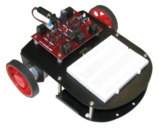
The original eBOT platform: chassis, motors, controller board area and breadboard workspace.
- A two-level chassis.
- Two geared DC motors compatible with the chassis.
- A motor driver that can control two DC geared motors in both directions.
- One breadboard for rapid prototyping of electronic circuits.
- One 4×1 battery holder.
- Wire stripper, multimeter and screwdriver.
- Electronic components such as ICs, sensors, a resistor box and capacitor box — all that you’d need to create autonomous bots.
- This manual.
- A great experience knowing you made your first autonomous robot!
You think you can follow this line!?
Dude! I can even follow you!!
LOGIC — How Can I Make Us Both Agree?
Imagine you’re two people living in a single room.
Both of you have access to just one light bulb.
It has been creating trouble for you that you can’t agree as to whether the light bulb should be turned on or off at any given time.
So you come up with a solution:
If and only if both of you need the light bulb, it should be on.
So you both get a switch each.
You’ve got to now wire it up to make this “logic” work.
How do you do it?
Well of course all of you know the answer is very simple.
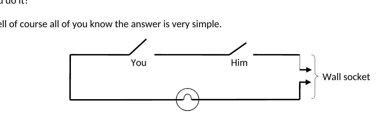
Two switches in series: the original manual introducing AND logic through a light-bulb problem.
The very famous AND gate!
Logic gates, as they’re called, are the most important building units to implementing logic.
The logic of how a problem’s solution should be designed.
Whenever we’re trying to find a solution to a problem, we most probably always know how to do it on our own, using our own mental faculties — the brain.
But that’s not really why we were in the first place finding a solution.
The real reason was to make something more primitive do the thinking for us in the long run.
Something such as a machine, a computer or a ROBOT.
So in designing or creating logic or algorithms, we should break down the steps we take for granted that allow us to make decisions.
Logic gates allow us to realize those steps we take to reach certain conclusions.
When we say:
I can only have a shower if I have water AND (soap OR bodywash).
We’re unconsciously using logic gates.
Some of the most basic logic gates are:
- AND GATE — all inputs should be true for output to be true.
- OR GATE — any one input should be true for output to be true.
- NOT GATE — changes true to false and vice versa.
- XOR GATE — allows only one input to be true in the two-input case.
Logic gates can be realized using switches — manual — or other electronic circuitry such as transistors and FETs.
The thing we need to know is that logic gates help us create logic.
They also sometimes help us store memory.
More on that later.
Memory is of primary importance in building logic.
A K-map is an important tool that helps remove redundancy in our logic-gate usage in a particular situation.
After finalizing our logic-gate circuit, we implement it using electronics.
Introduction to Electronics
Those of you who’ve ever used an iPod know how amazing it performs.
Just holding that thing in your palm makes you feel complete.
2026 ASIDE
It was 2007.
You had to be there.
How does it do it?
Making you hear crisp clear songs and making you see amazingly clear videos.
Where does it have the energy to do all that?
Ah!
Energy.
Energy source…
Battery.
Chemicals!!!
Oh.
Lithium-ion battery.
Electronics or electronic circuits are just like roads for electrons!
[Original explanation continues here.]
2026 CAVEAT — Do not take the road analogy too literally
The original text describes electrons as effectively giving up their kinetic energy to lamps, LEDs and motors.
That is not a good literal description of electrical energy transfer.
Charges move through the conductor, but useful energy is delivered through the electromagnetic field established by the source and circuit. In an LED, for example, light is produced through electron-hole recombination rather than a conduction electron simply surrendering its drift kinetic energy like a tiny billiard ball.
The road analogy remains useful for basic circuit intuition.
Just remember:
analogies eventually break.
A Non-Exhaustive List of Electronic Components
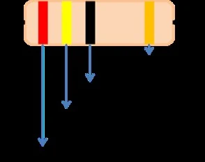
Original resistor color-band reference from the components section.
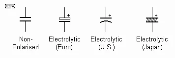
Original capacitor symbol reference.
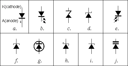
Original diode family symbol reference.
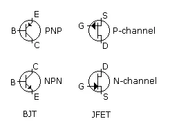
Original BJT and JFET transistor type reference.
- Resistors
- Capacitors
- Inductors
- Memristors
- Semiconductor devices
- Diodes
- Transistors
- Solar cells
- ICs
- Memories
- Sensors
- Switches
- Wire coils and magnets
- Vacuum tubes
2026 CORRECTION — Vacuum tubes
Vacuum tubes appeared beneath the semiconductor branch in the original diagram.
They are electronic devices.
They are emphatically not semiconductor devices.
Young Omar knew this.
Weekend-writing Omar apparently did not care.
Some Important Concepts in Electronics
Voltage / Potential Difference
The original manual introduces voltage using a water-pipe and pump analogy.
The useful intuition is simple:
A source creates a potential difference that can drive charge through a circuit, much as a pressure difference can drive water through a pipe.
The analogy then extends to common components:
- a resistor as a partially closed tap;
- a capacitor as a storage system;
- a transistor as a controlled valve.
2026 CAVEAT — The capacitor water tank
The original analogy says the capacitor behaves like a tank whose valve opens only when the tank becomes completely full.
That goes one step too far.
A capacitor does not wait until it is “full” before doing something.
Current flows while the capacitor charges and generally decreases as its voltage approaches the applied voltage.
Keep the idea of storage and changing potential.
Lose the magical valve.
Current
Current is the flow of electric charge.
2026 CORRECTION
The original calls current “the number of electrons that flow per second.”
More precisely:
[ I=\frac{dQ}{dt} ]
Current is charge per unit time.
In metallic conductors the moving charge carriers are electrons. In semiconductor devices, descriptions can involve electrons and holes.
The original current examples were also far too specific. A small indicator LED might run at only a few milliamps; a high-power LED may use hundreds of milliamps or more. A microcontroller may consume microamps while asleep and many milliamps while active.
Read the datasheet.
The datasheet is your friend.
Which way does current flow?
2026 CAVEAT
There is a defined conventional-current direction.
Conventional current flows in the direction positive charge would move.
In metallic conductors, electron drift is in the opposite direction.
The practical point younger-me was trying to make was much simpler:
choose a convention and remain consistent.
Physics does not care whether the arrows offend you.
Ohm’s Law
[ I=\frac{V}{R} ]
Simple.
Not all devices are ohmic.
But the relationship is enormously useful.
Power
[ P=\frac{W}{t} ]
and electrically:
[ P=VI ]
The unit of power is the watt.
Batteries
The original manual discusses battery voltage and ampere-hour capacity.
2026 CORRECTION — Ah is not maximum current
Ampere-hours tell you approximately how much charge capacity a battery can deliver.
They do not, by themselves, tell you the maximum current that battery can safely supply.
Maximum discharge current depends on chemistry, construction, internal resistance, thermal limits and the manufacturer’s rating.
Once again:
datasheet.
Signals
Real-world information frequently arrives in electronics as a varying voltage or current.
Sound.
Light.
Motion.
Pressure.
Temperature.
Signals can be analog or digital.
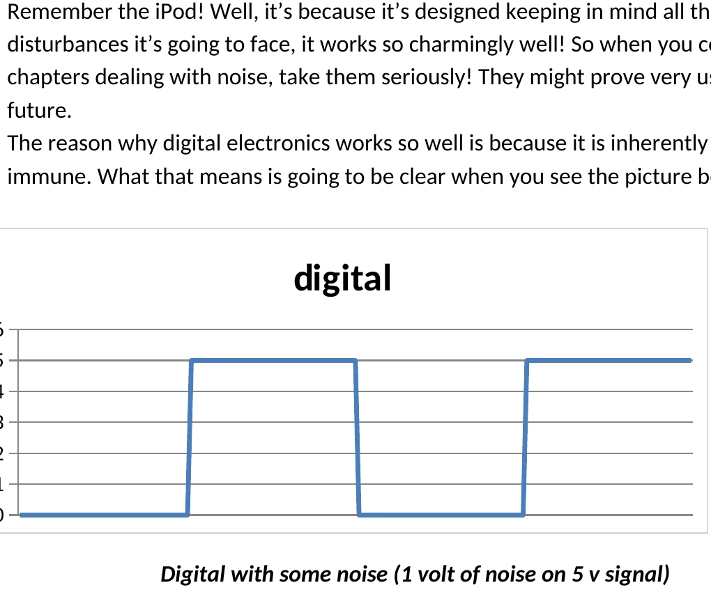
The original signal sketch contrasting idealized digital transitions with noisy real-world behavior.
The important point is not merely what a signal is, but what information it carries and what we want the circuit to do with it.
Noise
Every wire hanging from your circuit is, to some degree, an antenna.
Motors switch.
Power supplies ripple.
Radio transmitters transmit.
Signals couple into places you wish they wouldn’t.
That unwanted disturbance is noise.
2026 CAVEAT — Digital noise immunity
Digital electronics is not magically immune to noise.
It is generally tolerant of a useful amount of noise because valid logic levels are separated by noise margins.
If the disturbance becomes large enough to cross a logic threshold, your beautifully clean 1 becomes a 0 and your robot develops opinions.
Also, the voltage thresholds shown in the original graph were illustrative, not universal. Actual valid input/output ranges depend on the logic family and supply voltage.
THE ROAD MAP
Remember.
We promised a road map!
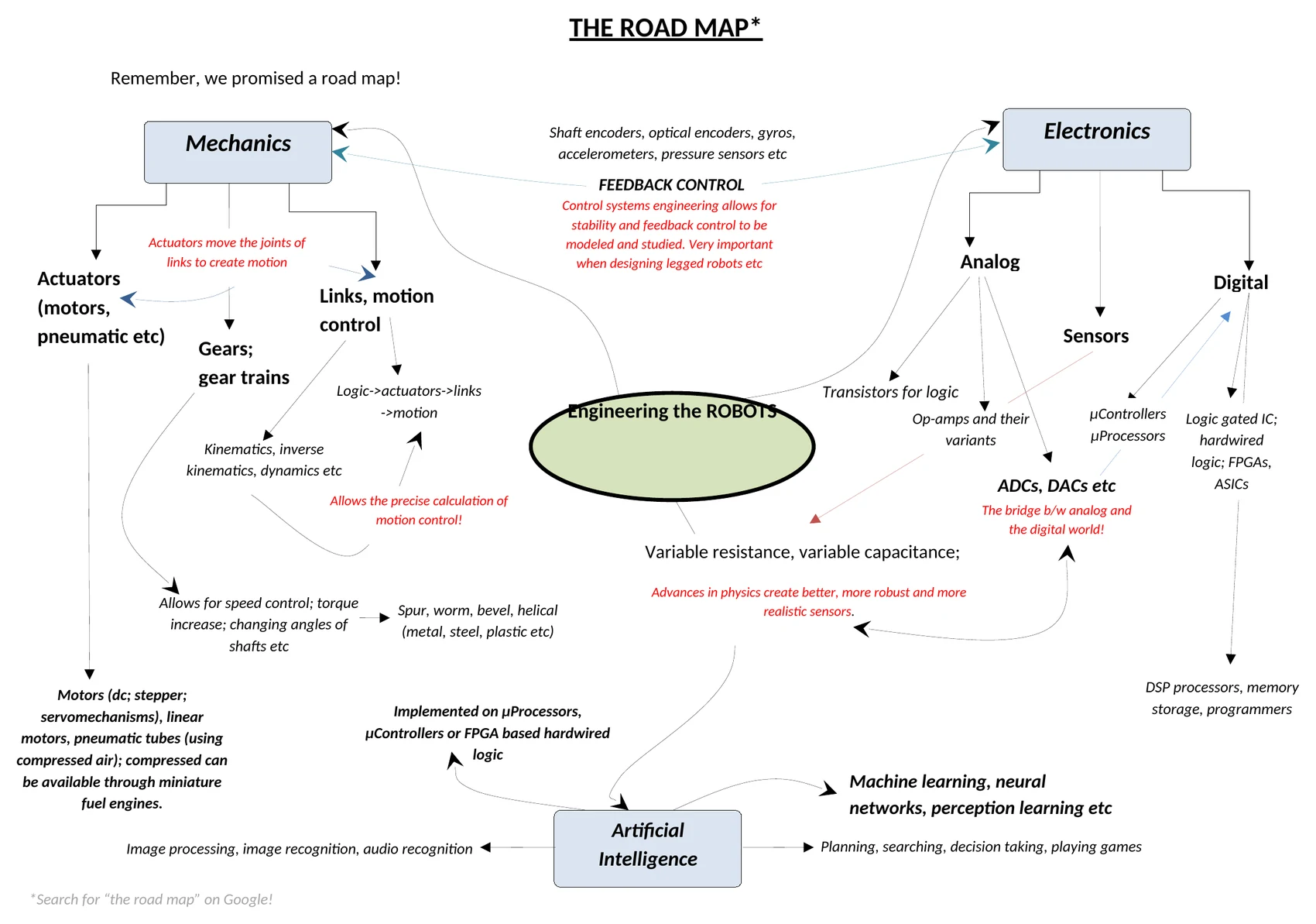
The original gloriously ambitious eTRIx Road Map.
The original diagram connects:
- Electronics
- analog
- digital
- sensors
- transistors
- op-amps
- ADCs and DACs
- microcontrollers
- processors
- FPGAs and ASICs
- Mechanics
- actuators
- gears
- links
- kinematics
- dynamics
- Feedback Control
- encoders
- gyros
- accelerometers
- stability
- Artificial Intelligence
- image processing
- image recognition
- audio recognition
- planning
- search
- decision-making
- machine learning
- neural networks
- perception
And beneath the whole thing, in the original:
Search for “the road map” on Google!
2026 ASIDE
This footnote remains untouched.
Those who know, know.
Those who do not are welcome to follow the original instructions and discover what 2000s Google does to an innocent engineering student.
The Basic Components
Resistors
Resistors are among the simplest and most useful components in electronics.
Common forms include:
- carbon film;
- metal film;
- wire wound;
- variable resistors;
- potentiometers;
- rheostats;
- LDRs;
- thermistors;
- strain gauges.
For an ohmic resistor:
[ R=\frac{V}{I} ]
Resistors have maximum power ratings.
They come in through-hole and surface-mount packages.
Common uses include:
- limiting current;
- forming voltage dividers;
- current-to-voltage conversion;
- bridge circuits;
- sensor calibration;
- filters;
- timing circuits.
2026 CAVEAT — “A resistor drops voltage and current remains the same”
That statement is true in the simple series circuit being discussed in the original section.
It is not a universal property of every resistor in every circuit.
Voltage and current depend on the surrounding network.
Kirchhoff is still lurking nearby.
Resistor Color Coding
| Color | Digit | Multiplier | Typical tolerance |
|---|---|---|---|
| Black | 0 | 1 | — |
| Brown | 1 | 10 | ±1% |
| Red | 2 | 100 | ±2% |
| Orange | 3 | 1k | — |
| Yellow | 4 | 10k | — |
| Green | 5 | 100k | ±0.5% |
| Blue | 6 | 1M | ±0.25% |
| Violet | 7 | 10M | ±0.1% |
| Grey | 8 | 100M | ±0.05% |
| Gold | — | 0.1 | ±5% |
| Silver | — | 0.01 | ±10% |
Capacitors
Before telling you that capacitors are polarized and non-polarized, let’s understand what a capacitor really does.
The original manual rather dramatically announces:
Capacitors don’t store “CHARGE”. NO! They store ENERGY.
2026 CORRECTION
I was trying to stop students imagining a capacitor as a bucket full of spare electrons and overcorrected.
A charged capacitor has equal and opposite separated charge on its plates, while energy is stored in the associated electric field.
[ E=\frac{1}{2}CV^2 ]
So yes:
a capacitor stores separated charge and energy.
Twenty-something me was yelling “NO!” much too confidently.
A capacitor consists, in its simplest conceptual form, of conductive plates separated by a dielectric.
Capacitance depends on geometry and dielectric properties.
2026 CORRECTION — “magnetic permittivity”
The original says capacitance depends upon the dielectric medium’s magnetic permittivity.
Nope.
Electric permittivity.
And plate separation matters:
[ C=\frac{\varepsilon A}{d} ]
where:
- (A) is plate area;
- (\varepsilon) is dielectric permittivity;
- (d) is plate separation.
This one is simply a mistake.
No philosophical rescue available.
Common capacitor types include:
- ceramic;
- film;
- electrolytic;
- tantalum.
Common applications include:
- coupling and decoupling;
- ripple filtering;
- timing circuits;
- oscillators;
- filters;
- energy storage;
- snubbers;
- sensing;
- RF tuning.
Semiconductors
Remember, in the Logic section we discussed how switches can be used to mimic logical behaviour.
The problem with switches is that they remain manual.
So:
How do we automate our system?
How do we make switches turn on and off on their own?
And besides…
how small can we make switches anyway?
Diodes
A diode can be thought of, at first approximation, as a device which strongly favors current flow in one direction.
That gives us an extraordinary number of uses.
Different diode families include:
- standard rectifier diodes;
- LEDs;
- Zener diodes;
- photodiodes;
- Schottky diodes;
- varactors;
- tunnel diodes;
- and many others.
Common uses include:
- rectification;
- clipping;
- clamping;
- reverse-polarity protection;
- flyback protection;
- voltage references;
- light emission;
- optical sensing;
- modulation and demodulation.
How to Think of a Diode
Whenever you find yourself wanting to create one-way traffic for your current path…
think diode.
When you need a nonlinear device that behaves differently depending upon voltage polarity…
think diode.
When some physical phenomenon — light, voltage, temperature, RF — can exploit a specialized junction…
look for the diode designed around that phenomenon.
And always read the datasheet.
2026 CORRECTION — LEDs are not 0.01 Ω switches
The original claims an LED essentially becomes a 0.01 Ω closed switch when forward biased.
That is not a useful model.
An LED is a nonlinear semiconductor junction with a forward-voltage/current relationship that becomes very steep once it begins conducting strongly.
The series resistor limits current to a safe value.
And yes, the resistor may be placed on either side of the LED in a simple series circuit because both components carry the same current.
Not because current “flows both ways.”
That sentence deserves to be dragged into an alley and dealt with.
THINK OVER IT!
Now we have something resembling an automated switch.
Can we combine such components to create logic?
Can we make a circuit whose output becomes HIGH only under some combination of inputs?
Can we control another circuit electrically?
We are rapidly approaching the component we actually want.
Welcome:
TRANSISTORS
Two broad transistor families you will meet constantly are:
- BJT — Bipolar Junction Transistor
- FET — Field Effect Transistor
Transistors are amplifiers!
No, NO!!!
Transistors are switches!
No man, transistors are basically controlled sources!
What!?
What answer is right?
Who should you listen to?
In fact, all these answers can be useful depending upon what level and operating regime you are discussing.
The point is not merely to memorize a definition.
The point is to understand what the device lets you do.
2026 CAVEAT — What is a transistor?
The original “switch! amplifier! controlled source!” argument remains one of my favorite parts of this manual.
The only thing I would change is the implication that every transistor can be collapsed into one generic current-controlled voltage-source model.
BJTs and FETs behave differently enough that this description should remain conceptual rather than literal.
The deeper lesson survives:
the same physical device can be understood differently depending on the role it plays in the circuit.
Transistors can be used as:
- controlled switches;
- amplifiers;
- building blocks for logic;
- memory elements;
- motor drivers;
- modulation circuits;
- sensor interfaces;
- analog circuitry;
- digital circuitry.
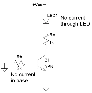
Original transistor-as-switch diagram with no base current and no LED current.
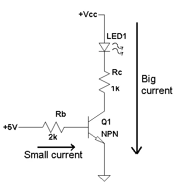
Original transistor-as-switch diagram with base current allowing LED current.
2026 HISTORICAL NOTE — Lilienfeld
Julius Edgar Lilienfeld patented field-effect transistor concepts in the 1920s.
The first demonstrated working transistor at Bell Labs was the point-contact transistor constructed by John Bardeen and Walter Brattain in 1947, followed by William Shockley’s junction-transistor work.
The history is more complicated — and much more interesting — than the original one-line summary suggested.
Sensors
Remember the road map?
We spoke of feedback control.
Feedback means feeding information from the surroundings back into the system so the robot can decide what to do next.
So we need an interface between the real world and the logical world.
For that we use sensors.
Take a simple example.
You are a ROBOT.
You have to play table tennis with a human opponent.
You need:
- a camera to see;
- a manipulator to hold and move the racket;
- knowledge of the racket’s position;
- knowledge of its orientation;
- information about the incoming ball;
- information about how hard you are hitting it.
That is a lot of information.
Before a robot can act intelligently, it has to acquire useful information about the world.
Sensors are transducers.
They convert some physical phenomenon into information our circuit can use.
Examples include:
Proximity
- tactile switches;
- reflective IR;
- visible light;
- ultrasound.
Environment
- light;
- temperature;
- pressure;
- gases;
- humidity.
Motion and Orientation
- gyroscopes;
- accelerometers;
- encoders;
- tilt sensors.
Image and Audio
- image sensors;
- microphones.
The eBOT Sensors
LDR — Light Dependent Resistor
An LDR changes resistance according to the amount of incident light.
A simple voltage divider lets us convert that resistance change into a voltage our logic can compare.

Original LDR symbol from the sensor section.
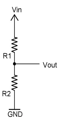
The original voltage divider used to turn changing resistance into a usable voltage.
For a divider:
[ I=\frac{V_{in}}{R_1+R_2} ]
and:
[ V_{out}=V_{in}\frac{R_2}{R_1+R_2} ]
2026 CORRECTION — Parentheses save lives
The equations in the original PDF were typeset ambiguously as though:
5 / R1 + R2were equivalent to:
5 / (R1 + R2)They are not.
Please do not design your robot using ambiguous algebra.
Photodiode
2026 CORRECTION
The original manual describes a photodiode essentially as a faster LDR-like variable resistor.
That is not the best model.
A more useful beginner model is a light-dependent photocurrent source.
Incident photons generate carriers, producing photocurrent. Reverse bias is commonly used because it improves speed and junction behavior for sensing.
That current can then be converted into a voltage for a comparator or processing circuit.
The original practical lesson survives:
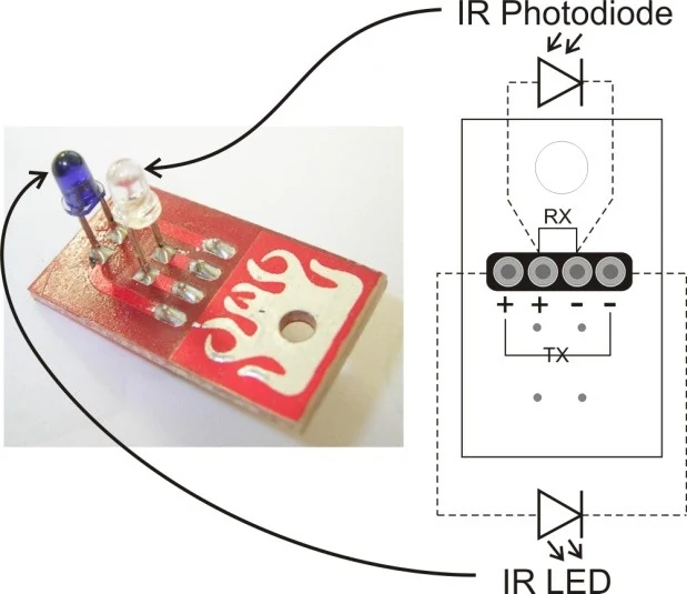
Original eBOT reflective IR sensor board showing the IR LED and photodiode pair.
photodiodes are dramatically faster than LDRs.
Ambient IR
2026 CAVEAT
Sunlight and incandescent sources absolutely can interfere with simple near-IR sensing.
But ordinary room-temperature objects emit most of their thermal radiation at considerably longer infrared wavelengths than the near-IR silicon detectors commonly used around 850–950 nm.
So the practical enemy is not every warm chair in the room secretly screaming infrared into your sensor.
It is ambient optical background in the detector’s usable spectral range.
Microphone
The eBOT used a simple microphone as an audio/pressure sensor.
Its signal can be amplified and turned into a logical event.
Which will become useful later when we make the robot react to a clap.
PROBLEM: The Flashlight Corridor
You’re at one end of a corridor, and your friend is at the other.
The corridor is dark.
You both want to talk.
To tell each other you’re there, you both have flashlights that you flash back and forth.
For a long time, you both enjoy the privacy of your conversation.
Then many more people enter the corridor and begin flashing lights everywhere.
Suddenly nobody knows which flashes belong to whom.
What do you do?
You could use another color.
But suppose everyone gets only white light.
You need another property by which your receiver can identify your transmitter.
You modulate.
2026 ASIDE — Why this analogy survives
Notice the order.
First the communication system fails.
Then modulation is introduced.
The student experiences the need for the concept before learning its name.
I did this repeatedly throughout the manual without consciously realizing why.
Years later I recognized something I had absorbed from Feynman:
knowing the name of a thing is not the same as understanding the thing.
TSOP1738
The TSOP1738 is an infrared receiver module designed to respond to IR modulated around 38 kHz.
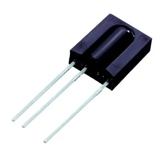
Original TSOP-style infrared receiver component photo.
Instead of accepting any optical disturbance as a valid signal, it performs filtering and conditioning internally.
That lets our system distinguish our deliberately modulated IR transmitter from much of the optical background.
This is extraordinarily useful for:
- remote controls;
- proximity detection;
- obstacle sensing;
- edge detection;
- simple encoded communication.
2026 CAVEAT — “Not affected by ambient light”
Too strong.
Modulated IR receivers reject steady ambient light and unrelated optical signals extremely well.
But strong sunlight, saturation or interference near the expected carrier frequency can still reduce performance.
Engineering rule:
“immune” usually means “you have not yet annoyed it enough.”
Ultrasonic Sensors
SONAR.
Ships use it.
Bats use echolocation.
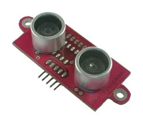
Original ultrasonic range sensor module from the sensor section.
Ultrasound machines use related physical principles.
You transmit sound at frequencies above normal human hearing.
It propagates through the environment, reflects from an object and returns.
If we know propagation speed and measure round-trip time, we can estimate distance:
[ d = \frac{v t}{2} ]
The division by two appears because the sound travelled to the obstacle and back.
Ultrasonic sensing can provide:
- range;
- relative motion information;
- object presence;
- sometimes directional information depending on the sensor configuration.
2026 CORRECTION — Bats
Bats are not blind.
Many species see perfectly well and echolocate.
I was repeating a common myth here.
Somewhere, a bat has been waiting nearly twenty years for this correction.
Okay, But Where Is My ROBOT?
We’ve talked about sensors.
Electronics.
Logic.
Components.
Apparently this was a manual that teaches you how to make autonomous robots, right?
Well…
yes.
But to know how to make robots, you need to know how to use the components that constitute your robot.
We’re almost there.
We have:
- electronic components;
- sensors;
- logic.
Now we need to turn those into decision-making circuits.
How to Make Logic Circuits
The best way is to first draw a flowchart or logical block diagram.
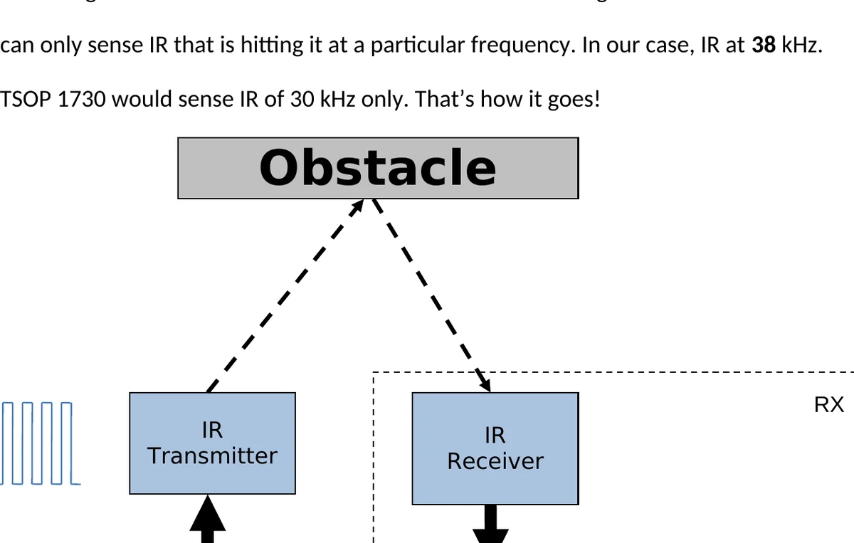
Original obstacle-avoidance logic flowchart showing sensor inputs feeding motor decisions.
Let us begin with a problem.
PROBLEM: Create a Robot That Sticks to a Wall
We need a sensor capable of detecting the wall.
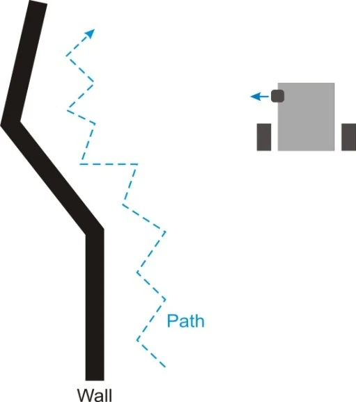
Original wall-following sketch: the robot continually corrects toward and away from the wall.
Then the logic can be:
- sensor sees wall → move away;
- sensor does not see wall → move toward it;
- repeat.
It is like a blind man continuously tapping the wall to ensure it is still there.
One motor can run when a wall is detected and the other when the wall disappears.
The robot oscillates around the desired distance.
A balancing act.
At least now you’re satisfied you can make a ROBOT with what you’ve learned so far.
But we can make much more interesting ones.
Line followers.
Clap-activated robots.
Light-seeking robots.
And to make those elegant…
we need something else.
The Wonderful Wizard of Op-Amp
“An operational amplifier, often called an op-amp, is a DC-coupled high-gain electronic voltage amplifier with differential inputs and, usually, a single output.”
That is perfectly respectable.
It is also a terrifying way to meet one.
We’d like to propose an alternative:
An op-amp is a tool that helps those building electronic circuits do the things they’d want to do.
It’s just like a sharp cutting knife.
Imagine you want to know what a knife does and we say:
A knife is an edged metallic alloy that has an angular curvature of 23 degrees.
Would you immediately think:
Aaah!
Now I can use that edged metallic alloy to cut my vegetables, open a screw when I can’t find my screwdriver, or sharpen my pencil!
No.
You understand the knife when you see what the knife lets you do.
That is the spirit in which we will approach the op-amp.
2026 TRIVIA UPDATE — The Wonderful Wizard
The original footnote called the Tin Woodman a fictional robot.
That is not quite right.
The Tin Woodman begins as a human and gradually has parts of his body replaced with tin, making him arguably closer to a cyborg.
L. Frank Baum later introduced Tik-Tok, a mechanical man, in Ozma of Oz (1907), who fits the modern robot idea much more cleanly.
So the joke stays.
The footnote gets better.
The Op-Amp
An op-amp is not a single transistor.
It is an entire circuit made from many transistors and other components.
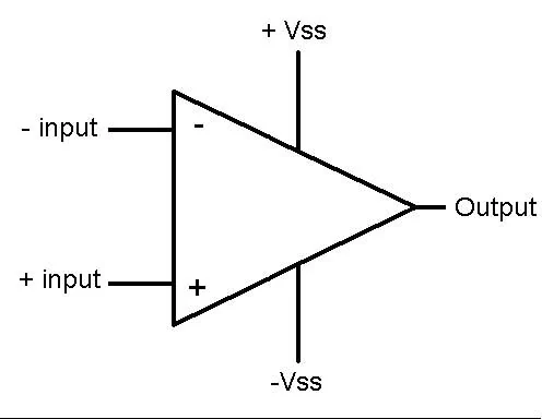
Original op-amp symbol and input/output reference.
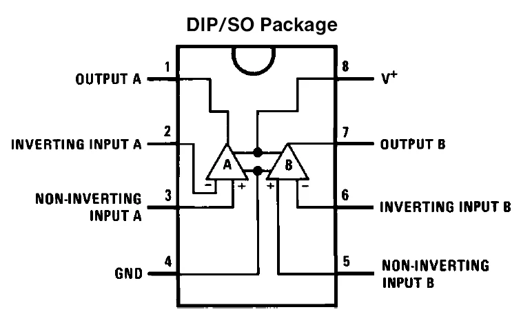
Original LM358 pinout and dual op-amp package reference.
Its most basic conceptual behavior begins with two inputs.
It responds to the difference between them.
2026 CAVEAT — Differential gain
An op-amp does amplify the voltage difference between its two inputs.
But in open-loop operation, its gain is enormous.
Therefore even a tiny input difference will normally drive the output toward one of the supply rails.
The really useful magic comes from feedback, which allows us to trade enormous uncontrolled open-loop gain for predictable closed-loop behavior.
Which, incidentally, is the more interesting story anyway.
Useful op-amp configurations include:
- amplifiers;
- comparators;
- buffers;
- filters;
- oscillators;
- integrators;
- differentiators;
- instrumentation amplifiers;
- precision rectifiers;
- current-to-voltage converters.
2026 CORRECTION — Gain vs supply voltage
The original says real-life gain is “limited to the voltage present at +Vss/-Vss.”
No.
The supply voltage limits the output swing, not the numerical gain itself.
Real op-amps have:
- finite open-loop gain;
- finite bandwidth;
- input offset;
- input common-mode limits;
- output-current limits;
- slew-rate limits.
Welcome back to that dusty textbook.
Integrators and Differentiators
Here comes the class of physics you never paid attention to.
Velocity relates to the derivative of position:
[ v=\frac{dx}{dt} ]
and therefore displacement can be obtained by integrating velocity:
[ x(t)=\int v(t),dt ]
2026 CORRECTION
The original preceding sentence says:
distance = speed / timeIt should of course be:
[ d=v,t ]
Yes.
I knew this.
I promise.
I probably wrote this page at 3:00 a.m.
Op-Amps as ICs
Go to an electronics shop and ask for “an op-amp.”
The shopkeeper will get frustrated with you.
Which one?
Examples commonly encountered in the original workshop included:
- 741;
- LM358;
- LM324;
- dedicated comparator and instrumentation devices.
The eBOT used the LM358.
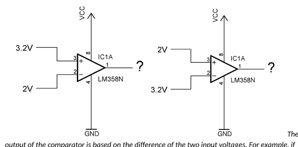
Original LM358 comparator examples comparing two input voltages.
The important modern lesson remains:
Do not select a component merely by remembering a part number from class.
Determine what your circuit requires.
Then read datasheets and application notes.
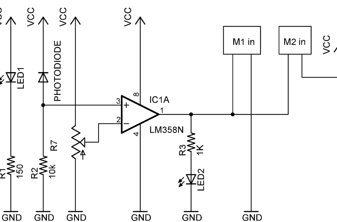
Original sensor comparator circuit that bridges the op-amp section into the line-follower build.
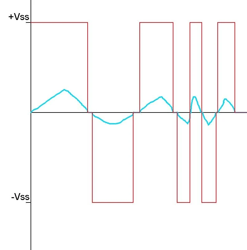
Original comparator waveform sketch showing analog input behavior producing a digital-style output.
The One-Sensor Line Follower
You have one optical sensor.
It can distinguish approximately:
- line;
- no line.
Can you make a robot follow the line using only that information?
Yes.
Crude logic:
- Sensor sees the line → turn away.
- Sensor loses the line → turn back toward it.
- Repeat.
The robot zigzags around the line but continues to follow it.
It’s crude.
But it works like a charm.
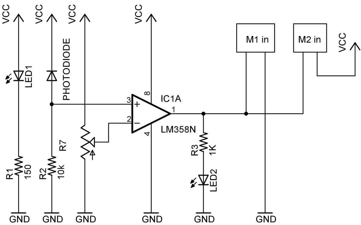
The original eBOT one-sensor line follower.
2026 ASIDE
I stand by the original recommendation:
Watch WALL-E.
Come back and look at the line-following robot again.
Pixar did not include the comparator schematic.
Actuators and Drivers
A robot that can sense and decide but cannot act is merely an unusually complicated observer.
We need actuators.
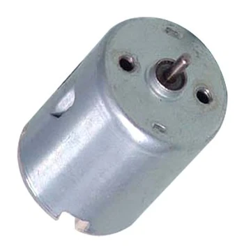
Original DC motor reference photo.
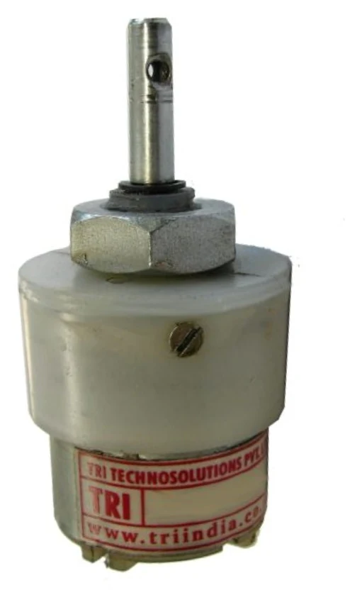
Original geared DC motor reference photo.
Common robotic actuators include:
- DC motors;
- geared motors;
- servos;
- stepper motors;
- linear actuators;
- pneumatic systems;
- various artificial-muscle technologies.
DC Motors
A useful beginner intuition is:
- applied voltage strongly influences motor speed;
- motor current strongly correlates with torque.
But the real behavior also involves:
- winding resistance;
- inductance;
- torque constant;
- back-EMF constant;
- load;
- friction;
- efficiency.
A motor spinning very quickly with no useful torque is not particularly helpful if your robot cannot move its own batteries.
So we use gears.
Gears trade angular speed for torque.
2026 CAVEAT — Current, speed and gears
The original text says that current consumed during the reduction is somehow “translated” into increased torque at the output gear.
The useful intuition survives.
But gears do not literally turn electrical current into mechanical torque.
The motor converts electrical energy into mechanical rotation.
The gear train then transforms mechanical angular speed and torque according to gear ratio, minus losses.
Servos
A servo combines motor, gearing and feedback/control so that a commanded signal corresponds to a desired shaft position or motion.
The hobby servos discussed in the original manual typically use pulse timing commands.
Stepper Motors
Stepper motors move in discrete commanded steps.
They are useful wherever controlled incremental motion is required.
2026 UPDATE — Stepper archaeology
“Four wires” is not universal. Different stepper winding configurations use different numbers of leads.
Also, early disk drives sometimes used stepper mechanisms for head positioning, while modern hard drives overwhelmingly use voice-coil actuators.
Floppy drives remain wonderfully electromechanical archaeological specimens and should be preserved for future children to poke.
Motor Drivers
Logic circuitry generally cannot supply enough current to drive a motor directly.
So we place a driver between the decision-making circuitry and the motor.
A transistor can act as that controlled power switch.
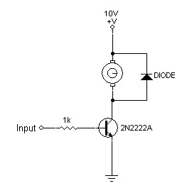
Original transistor motor-driver switch with flyback diode protection.
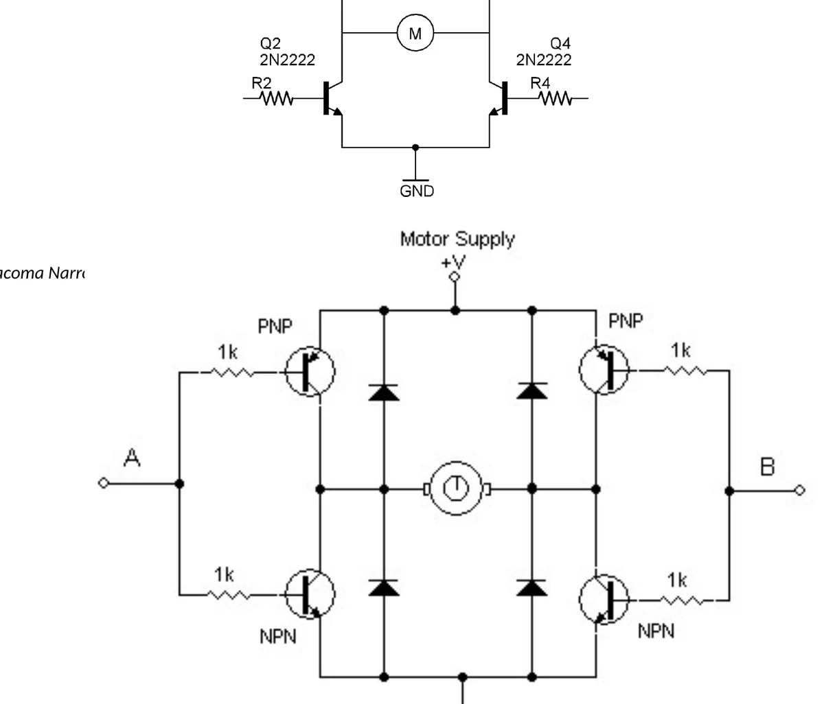
Original motor-driver input diagram showing how logic inputs determine motor behavior.
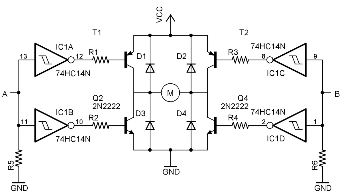
Original logic-gated motor-driver IC schematic from the manual.
Because motors are inductive loads, switching them can generate large voltage transients.
A flyback diode provides a safe current path and protects the switching device.
THE TACOMA NARROWS BRIDGE — With Feedback Diodes
Or:
How I Protected My H-BRIDGE MOTOR DRIVER
If we want to run a DC motor in both directions, we need to reverse the voltage across it.
An H-bridge gives us a switching topology that can do exactly that.
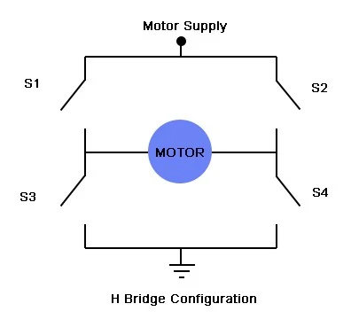
Original conceptual H-bridge switch layout for reversing a motor.
Close one diagonal pair of switches:
motor turns one way.
Close the opposite diagonal:
motor turns the other.
Replace the conceptual switches with transistors and suddenly our robot’s logic can control motor direction electrically.
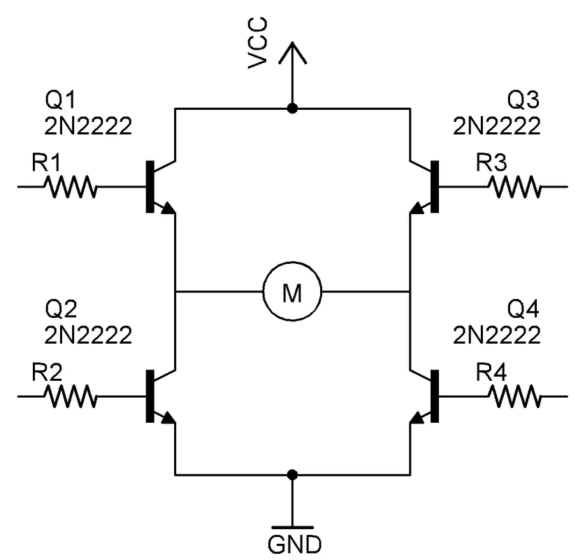
The original ‘Tacoma Narrows Bridge’ H-bridge section.
2026 ASIDE
Yes.
I introduced the H-bridge through the Tacoma Narrows Bridge, one of history’s most famous engineering failures.
No, this was not pedagogically necessary.
Yes, it remains in the book.
Also, the original heading misspelled Tacoma as Takoma.
Fixed after approximately eighteen years.
Thank God Hans Invented the Time Machine
Or:
The IC 555 — “THE IC TIME MACHINE”
Before we start explaining things like monostable multivibrators, trigger pins and threshold voltages, it’s time to sit back and realize what we’ve accomplished so far.
We started with problems.
Every time we introduced a familiar component, we tried to make it look like a tool.
Now we arrive at one of the finest little tools ever created.
The 555 timer.
Hans Camenzind designed the original 555 in 1971.
Its genius is partly that so many useful internal control points are made available externally.
The device can be configured for an absurd number of purposes.
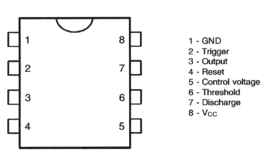
Original NE555 pinout reference.
Original 555 pin descriptions and timing notes.
Applications include:
- timers;
- monostable multivibrators;
- astable oscillators;
- pulse generation;
- PWM;
- pulse-position modulation;
- Schmitt-trigger behavior;
- tone generation;
- missing-pulse detection;
- assorted circuits nobody originally expected.
2026 ASIDE
More than half a century after Hans Camenzind designed it, engineers are still finding excuses to use the 555.
My admiration for this little bastard has not diminished.
If anything, I underestimated it.
2026 CAVEAT — “Open-source design”
The original calls the accessible 555 control pins “sort of like an open source design.”
I meant this metaphorically.
The 555 was not open-source hardware in the modern licensing sense.
What fascinated me was that Camenzind exposed useful internal control points to the circuit designer instead of hiding everything behind a fixed interface.
The analogy reveals something else about younger me, though.
I apparently wanted even integrated circuits to have APIs.
555 Timing
The quantity:
[ RC ]
has units of time and is the fundamental RC time constant.
The original manual casually writes:
[ t=RC ]
as general timing intuition.
For actual 555 configurations, the constants depend upon the topology.
Monostable Mode
For the common monostable configuration:
[ T\approx1.1RC ]
A trigger creates a single output pulse whose duration is determined by the timing components.

Original monostable trigger and output waveform.
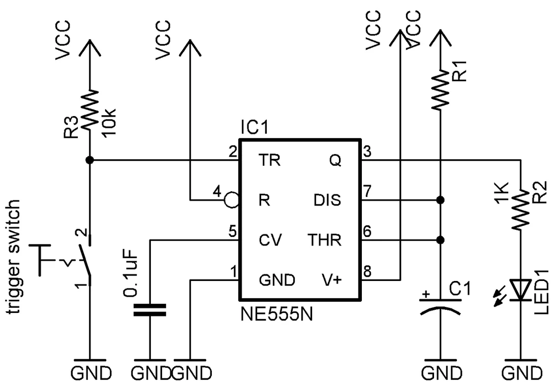
Original 555 monostable circuit diagram.
Applications include:
- timers;
- switch debouncing;
- pulse stretching;
- one-shot events;
- robot behaviors that should last for a fixed interval.
Clap Sensor
What if the trigger comes from sound?
A microphone gives us a small electrical signal.
A transistor stage can amplify the transient.
That pulse can then trigger logic.
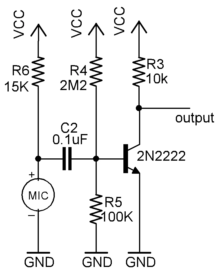
Original clap sensor circuit using a microphone and transistor stage.
Suddenly:
clap → electrical event → timer → motor behavior
We can make a robot:
- start when clapped;
- stop when clapped;
- turn when clapped.
Same components.
Different wiring.
Different behavior.
That is the entire point.
Astable Mode
In astable mode the 555 continuously oscillates.
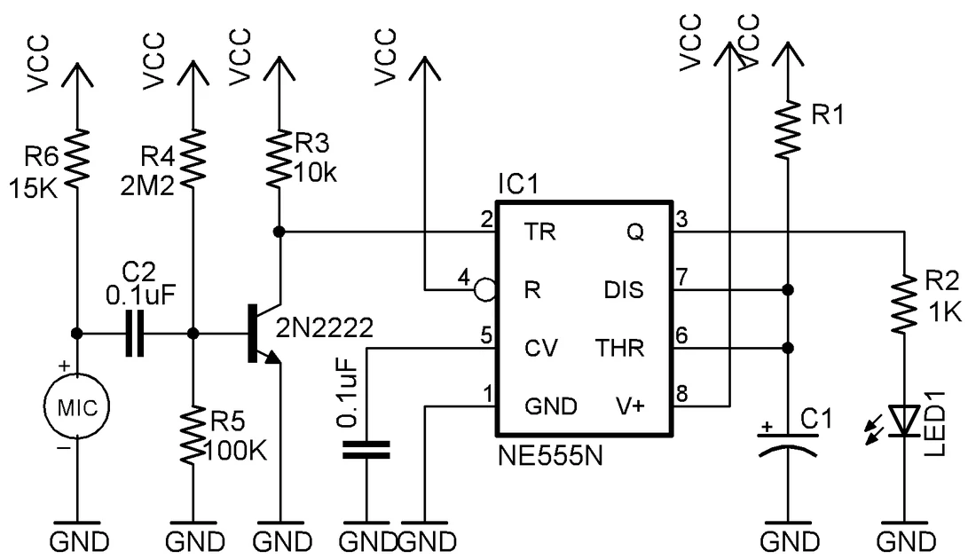
Original 555 astable oscillator circuit diagram.
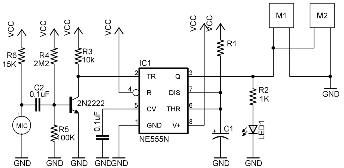
Original 555 astable extension showing motor-control use.
A common relationship is:
[ f=\frac{1}{0.693,C(R_1+2R_2)} ]
Applications include:
- signal generation;
- flashing lights;
- tone generation;
- modulation;
- PWM.
The capacitor normally charges and discharges through different resistance paths, giving unequal HIGH and LOW times.
Can you use a diode to create separate charge and discharge paths?
Think about it.
If you figure it out yourself…
“It will be a breakthrough of Gaussian proportion.”
2026 ASIDE
This is a reference to Sneakers (1992), still one of my favorite hacker films.
If you have not seen it, please stop reading the electronics manual and correct this deficiency.
The 555 will wait.
Modulated Sensors
Now we can finally connect several ideas.
Simple IR transmitter + detector pairs can be overwhelmed by ambient optical signals.
But we know how to generate an oscillator.
So:
- Configure the 555 around 38 kHz.
- Drive the IR LED with that modulation.
- Use a receiver designed to recognize that carrier.
- Ignore much of the unrelated optical background.
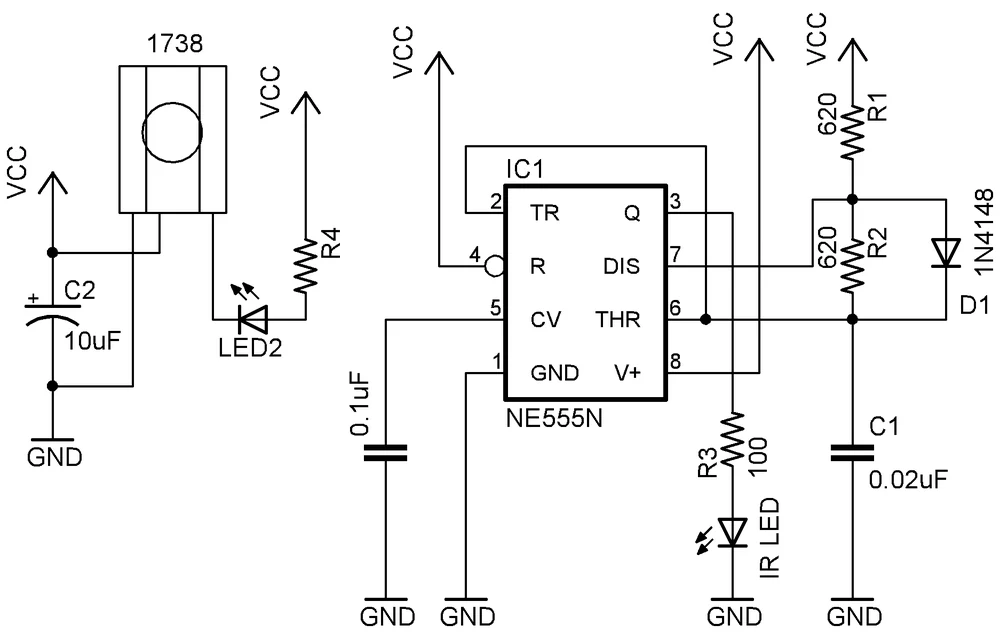
Original 555-based infrared transmitter circuit for modulated sensing.
The flashlight corridor has become a circuit.
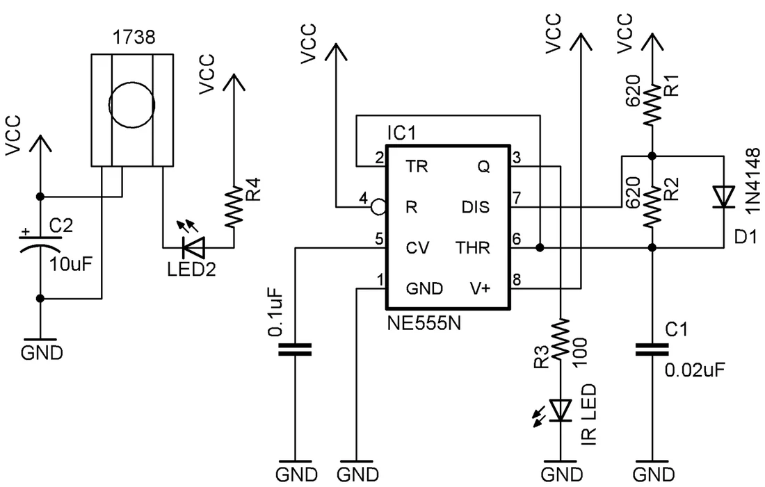
Original 555 modulated-IR circuit from the sensor section.
That is what I mean by using ideas as tools.
PWM — Pulse Width Modulation
PWM lets us switch a load rapidly while varying the proportion of time spent ON versus OFF.
This proportion is the duty cycle.
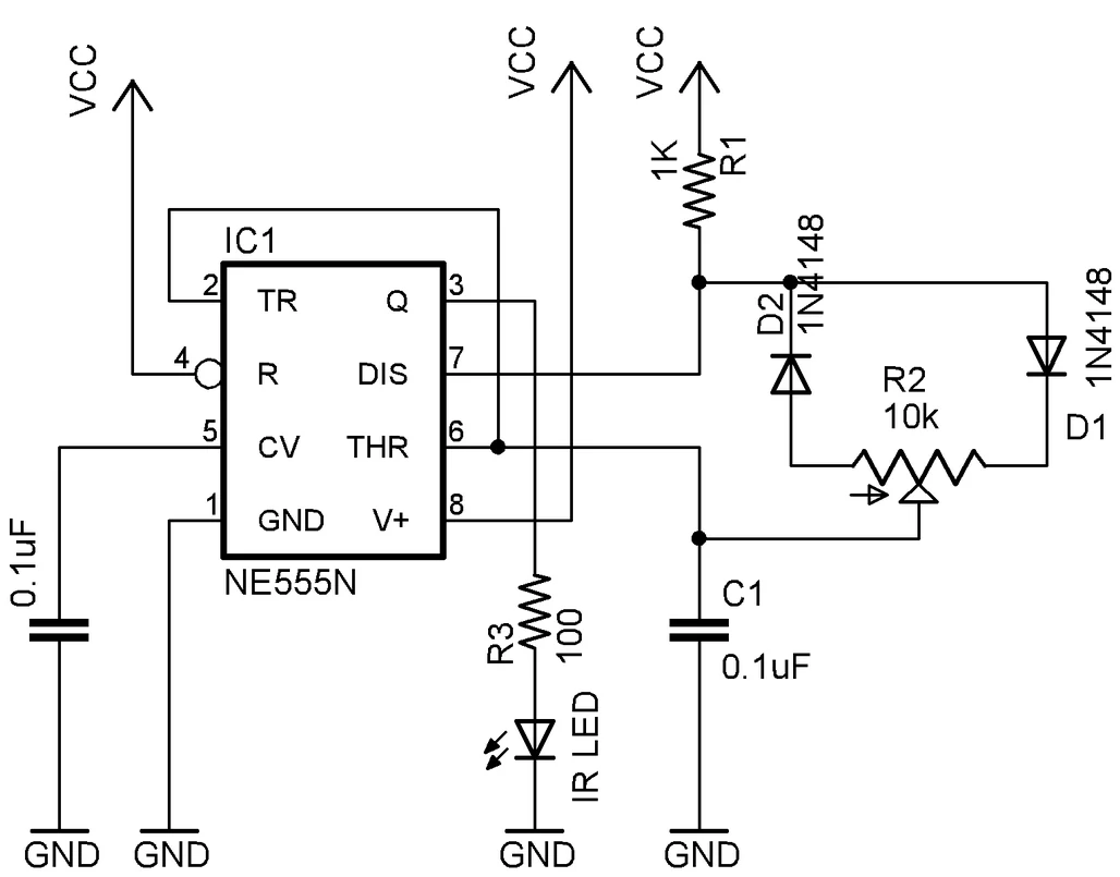
Original 555 PWM-style control circuit.
For motors, PWM provides a highly effective way to control average power and therefore speed.
2026 CAVEAT
The original says the motor “sees PWM as a voltage.”
Not literally.
The applied voltage is still switching between discrete levels.
But the motor’s winding inductance and mechanical inertia smooth the resulting electrical and mechanical response, so speed responds substantially to the average effect of the pulse train.
That is why PWM provides efficient speed control without throwing away large amounts of energy in a linear control element.
What Else Is My eBOT Capable Of?
We have now created or discussed:
- A one-sensor line follower.
- A two-sensor line follower.
- An obstacle detector/avoider.
- A clap-activated robot.
- Light-sensitive behavior.
- Timing.
- State.
- Motor direction.
- Motor speed.
- Sensor conditioning.
The point is no longer to copy circuits.
The point is to start combining tools.
TRY AT HOME — Problem Statements
- Make a robot traverse a rectangle whose side lengths can be set using two potentiometers.
- Modify the rectangle into a parallelogram by changing turning time.
- Control robot speed using light intensity.
- Make a robot alternate between left and right turns on successive claps.
- Make a robot turn exactly 90° or 180°, selectable using a switch.
- Build a cliff/edge detector to prevent the robot falling from a table.
- Build a line follower capable of navigating around an obstacle and returning to its path.
- Build a manually controlled robot which refuses commands that would drive it off a table.
- Build a variable-speed LED flasher.
- Build a simple servo-control signal generator using the 555.
- Use current sensing to detect whether a motor is stalled or freely rotating.
- Build a longer delay using a 555 and counter.
- Smooth a line follower so that correction slows a motor rather than stopping it completely.
- Build a rudimentary color sensor using an LDR and red, green and blue illumination.
- Build a wall follower.
- Build a capacitor meter using timing.
- Build a water/metal-sensing robot.
Major Project A — Sleep and Wake
Create a robot that begins in sleep mode.
A light trigger wakes it.
Once awake it remains awake even after the light disappears.
A clap puts it back to sleep.
Another light trigger wakes it again.
What does this require?
Not merely sensing.
It requires memory.
Major Project B — Try the Obstacle Once
Create a robot that detects an obstacle.
Instead of immediately avoiding it, the robot pushes against it once.
If the obstacle disappears, continue.
If it remains, stop, turn or sound a buzzer.
Now the robot’s behavior depends not merely on present sensor state but on the result of an attempt.
That is already a more interesting machine.
THE THIRD LAW OF ROBOTICS
The original heading here said:
THE THREE LAWS OF ROBOTICS
But the exercise was specifically:
build a robot that prevents its human operator from driving it off a table.
2026 LITERARY CORRECTION
This exercise is really invoking Asimov’s Third Law:
a robot should protect its own existence, provided doing so does not conflict with the higher-priority laws.
So the project is hereby renamed:
THE THIRD LAW OF ROBOTICS
Build a robot that refuses to let its idiot human drive it off the table.
Consider this corrected.
Current Sensing — Is the Motor Stalled?
A motor under heavy mechanical load draws substantially more current than it does while spinning freely.
That gives us information.
Put a known small resistance in the current path.
Measure the resulting voltage.
Now current has become a signal.
Feed that into a comparator.
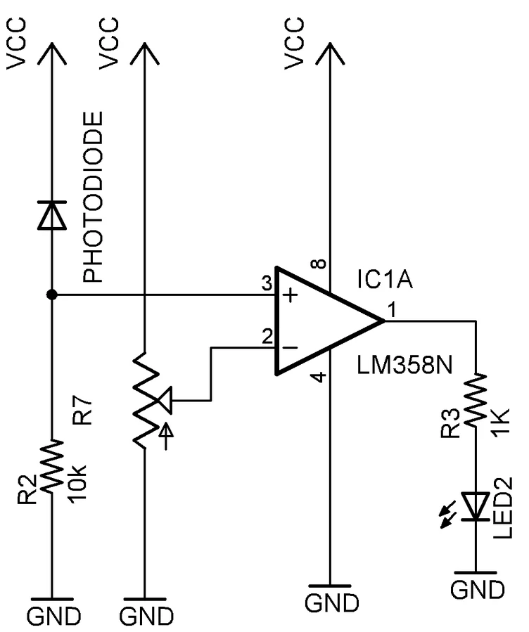
Original motor current-sensing comparator circuit.
Set a threshold.
Suddenly the robot can detect:
I am trying to move, but I am not moving.
This is an important transition in the manual.
The motor was previously just an actuator.
Now the motor itself provides information about what is happening mechanically.
The system begins to observe itself.
Smoothening a Line-Following Robot
The simplest line follower turns one motor completely off during correction.
That works.
But it wastes momentum and produces jerky motion.
So instead of:
- full speed;
- zero speed;
try:
- full speed;
- reduced speed.
A more graceful correction emerges.
This is a recurring engineering lesson:
The first solution proves the idea.
The next solution improves the behavior.
Major Project A — Memory
We want two persistent states:
- awake;
- asleep.
A momentary light event should place the machine in one state.
A momentary clap should place it in the other.
This is no longer merely a sensor problem.
It is a state problem.
A bistable circuit can remember which event happened last.
The 555 can be configured as a bistable latch.
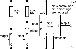
Original 555 bistable latch configuration for simple memory.
Now:
- light → set;
- clap → reset.
The system remembers.
Combine:
- sensor circuits;
- transistor switches;
- bistable logic;
- motor drivers;
and the robot acquires simple stateful behavior.
The Actual Lesson
Whenever you’re faced with problem statements like the ones above, use what you’ve learnt so far to solve them logically.
It might take some time to get used to this methodology.
But once you understand how to use it, you’ll be able to design circuits easily.
Always remember:
First draw a logical block diagram of the solution.
Then ask:
How can each block be implemented physically?
Capacitors.
Resistors.
Transistors.
Logic gates.
Op-amps.
Comparators.
Timers.
Sensors.
Motors.
Drivers.
Memory.
All of them are tools.
You do not begin with:
“Where can I use a 555?”
You begin with:
“I need this robot to wait for two seconds.”
And suddenly the 555 has a reason to exist.
That is how this manual was always supposed to work.
Happy Roboteering
The original manual ends:
Hope you’ve enjoyed and happy Roboteering!
2026 NOTE
Twenty years later, I still think this is the correct ending.
Happy Roboteering.
Afterword: A Note About the Password
When I left ThinkLabs in December 2008, I left this manual password-protected.
This was not an accident.
When management contacted me asking for the password, I told them I would provide it on one condition:
The manual should not simply become proprietary company intellectual property.
I wanted it shared under a copyleft philosophy — free to be used, studied, modified and passed along.
They were not immediately enthusiastic.
I was not immediately cooperative.
Eventually they agreed.
I gave them the password.
If memory serves, it was:
Richard Matthew Stallman
There are probably more mature ways to negotiate intellectual-property policy.
I was twenty-something.
This one worked.
One Last 2026 Note
There is something strangely appropriate about republishing the manual this way.
The mistakes have not been silently erased.
They remain visible beside the corrections.
Because that is what engineering actually looks like.
You build a model.
Reality corrects it.
You update the model.
Then you keep building.
Even when younger-you was behaving like a little shit…
…he was arguing that knowledge should remain hackable.